RepairMultiTool (RMT)
RepairMultiTool (RMT) is a universal multi-tool designed for repair, diagnostics, and emulation of electronic components and systems. It combines a 220V relay output, dry contact relay, UART interfaces, a programmable power supply (PPS), and up to 4 expansion submodules in a single compact device with an integrated display and encoder control.
Modular Architecture
RMT features a modular expansion system with 4 submodule slots. Each submodule is an independent board with its own functionality and microcontroller, connected to the main controller via the I2C bus. Submodules can be installed in any combination — up to 4 simultaneously — allowing the tester to be adapted to a wide range of tasks. New submodules will be released over time, expanding the capabilities of the platform without replacing the base device.
The firmware automatically detects installed submodules and enables the corresponding applications in the main menu.
Connector Pinout

The rear panel of the RMT provides the following connectors:
① Input 220VAC — mains power input for the tester.
② Output 220VAC — relay-switched 220V output for connecting loads controlled by the tester application. The relay is managed automatically by the firmware — no manual switching is required.
③ Dry Contact — galvanically isolated relay output (NO). Used when you need to emulate a button press or switch closure without providing power to the circuit (e.g., simulating a power button).
④ UART / Power — multi-function connector for communication and power. Provides UART interfaces (Active High / Active Low / Single Line), +5V power, GND, and PPS (Programmable Power Supply) output. See the pinout diagram for detailed pin assignments.
⑤ Submodule Slots — slots for connecting RMT submodules. See the documentation for each submodule.
Applications:
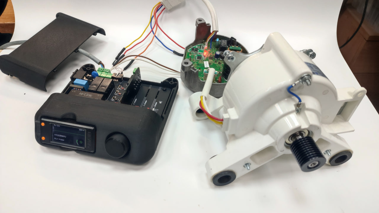
MotorPumpDrive
Motor and pump control application. Supports multiple motor types with UART communication:
- HK222861U — Single Line UART Active High
- ZXGN420 — UART via optocouplers (HP1/HP2)
- MDW Module — Module + Pump chain via H1 and STx bus
See the detailed guide for wiring diagrams and step-by-step launch instructions.
Power Supply (PPS)
Programmable power supply — a compact bench PSU built into the RMT. Voltage range 1.0–20.0V, auto-calculated current limit, up to 4.5W.
FlowMeter
Reed switch emulator and frequency recorder. Two isolated output channels (K1, K2), two input channels (Line 1, Line 2), session recording and playback. Frequency range 0.1–250 Hz.
Settings
System configuration — startup app selection, encoder type, 5V power unit control.
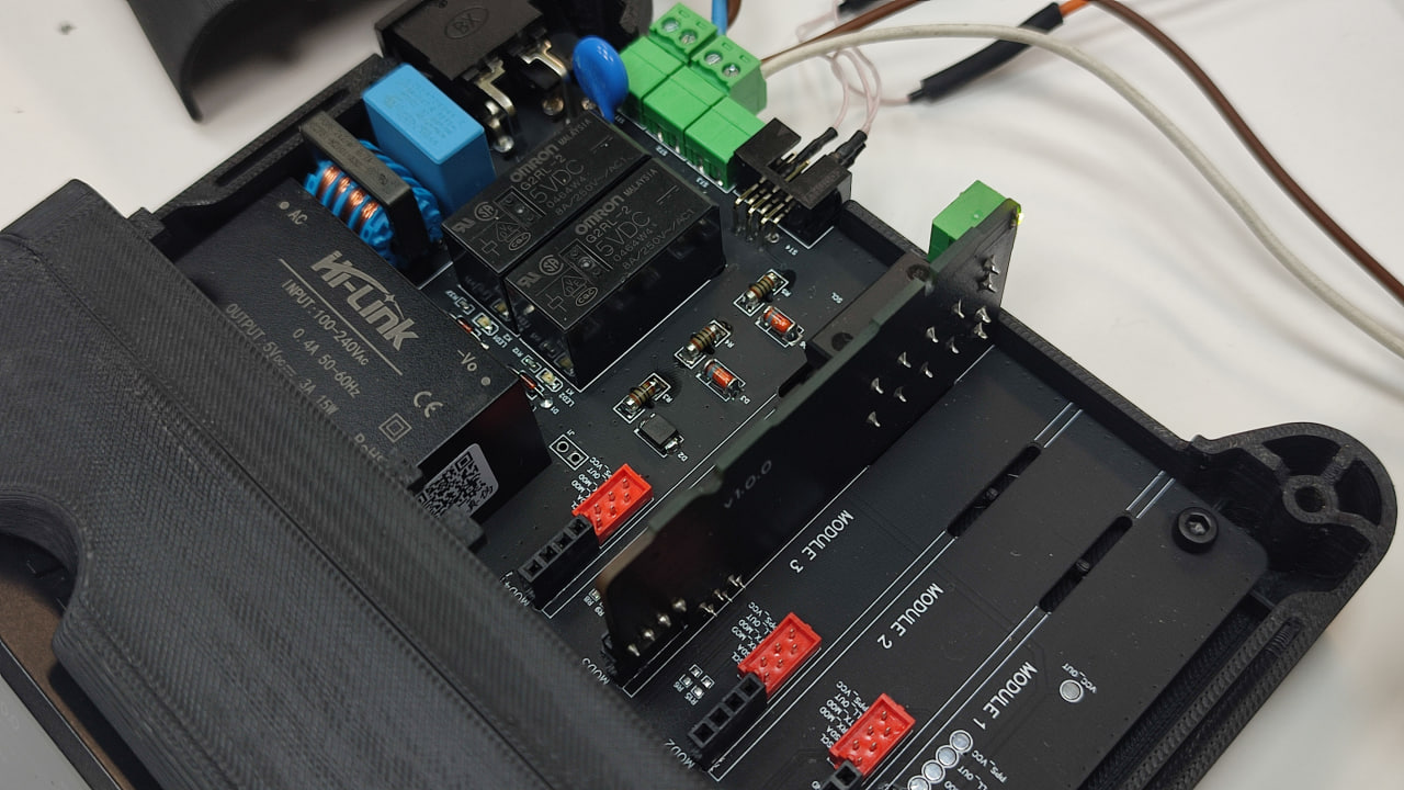
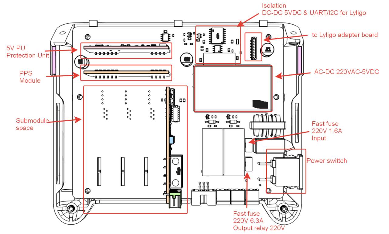
PCB Overview
Opening the Enclosure — Accessing the Submodules
To access the submodule slots, the top cover of the RMT needs to be removed.
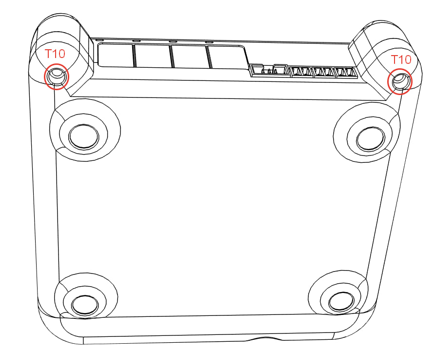
- Locate the two screws on the rear side of the enclosure — they are positioned on the protruding lugs (mounting ears).
- Unscrew both screws using a Torx T10 screwdriver.
- Lift the top cover upward.
- You now have access to all 4 submodule slots. A submodule can be installed into any of the available Module slots.