MotorPumpDrive
Motor and pump control application for RMT.
Supported Motors
| Motor | Interface | Wiring |
|---|---|---|
| HK222861U | UART Single Line Active High | ST.2 (220V) + ST.4 (Pin 3, 4, 6) |
| ZXGN420 | UART via optocouplers HP1/HP2 | ST.2 (220V) + ST.4 (Pin 1, 2, 4) |
| MDW Module | UART H1 + STx bus to Pump | ST.2 (220V) + ST.4 (Pin 1, 2, 4, 6) |
Wiring Diagrams
For the rear panel pinout, refer to the RMT overview.
HK222861U

RMT ST.2 → Motor 220VAC:
- L (Switched Line) → L motor
- N (Neutral) → N motor
RMT ST.4 → Motor UART:
- Pin 3 (UART Single Line Active High) → UART motor
- Pin 4 (GND) → GND motor
- Pin 6 (+5V) → +5V motor
ZXGN420

RMT ST.2 → Motor 220VAC:
- L (Switched Line) → L motor
- N (Neutral) → N motor
RMT ST.4 → Motor UART (optocoupled):
- Pin 1 (TX Active High) → RX ZXGN420 (HP2 — optocoupler designation on the board)
- Pin 2 (UART Active Low) → TX ZXGN420 (HP1 — optocoupler designation on the board)
- Pin 4 (GND) → both GND pins of ZXGN420
Inside the motor block (SWAN-BDM-M4) each optocoupler channel has its own ground return — HP2/RX and HP1/TX — so the ZXGN420 exposes two GND pins. Wire RMT ST.4 Pin 4 (GND) to both of them.
MDW (Module + Pump)
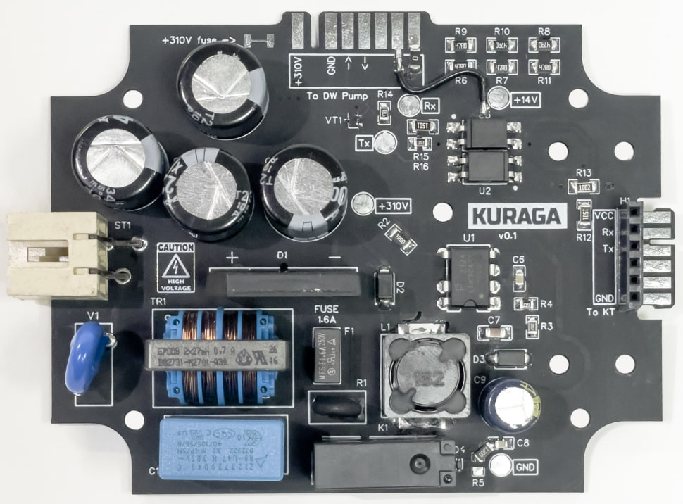

MDW uses a three-device chain: RMT → MDW Module → MDW Pump.
RMT ST.2 → Module ST1 (220VAC):
- L → L
- N → N
RMT ST.4 → Module H1 (UART):
- Pin 1 (TX) → H1.RX
- Pin 2 (RX) → H1.TX
- Pin 4 (GND) → H1.GND
- Pin 6 (+5V) → H1.VCC
Module STx → Pump STx:
| Module STx | Pump STx | Signal |
|---|---|---|
| STx.1 | STx.1 | 310VDC |
| STx.3 | STx.3 | GND |
| STx.4 | STx.4 | TX → RX |
| STx.5 | STx.5 | RX → TX |
| STx.6 | STx.6 | GND |
| STx.7 | STx.7 | 14VDC |
| STx.8 | STx.8 | 5V_14VDC |
Launching a Motor
Before starting, make sure the motor is properly wired to the RMT according to the diagrams above. Connect the RMT to 220V power supply.
- Turn on the RMT. The main menu will appear on the display.
- Using the encoder, navigate to MotorPumpDrive and press OK.
- Select the motor model from the list and press OK.
- The motor control screen will appear with:
- Setpoint — target speed, adjusted with the encoder.
- Feedback — actual value reported by the motor.
- Graph — real-time plot of setpoint vs. feedback, showing how the motor reaches and maintains the target speed.
- Status — current state (RUN / STOP / ERROR).

- Press OK to start the motor. Adjust the setpoint with the encoder.
- Press OK again to stop the motor.
The graph shows the speed achievement curve — how the motor ramps up to the setpoint. This is useful for diagnostics: a healthy motor should reach the target speed smoothly within a few seconds.
Controls
| Action | Control |
|---|---|
| Navigate menu | Rotate encoder |
| Select / Start / Stop | Press OK (center button) |
| Adjust setpoint | Rotate encoder (in motor control screen) |
| Go back | Press Back |
Always stop the motor before disconnecting any wires.