Adapter
The adapter can be assembled independently using the schematic (click to download), but this option is suitable only for experienced users. If you build the adapter yourself, you take responsibility for it and for debugging it.
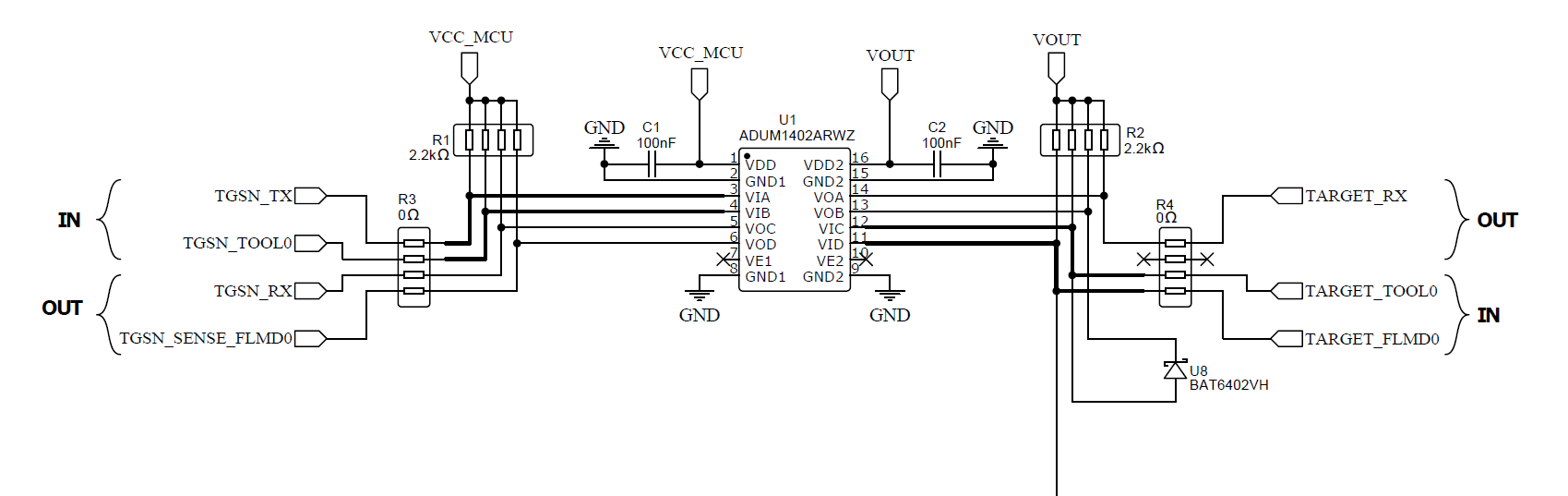
What's on the board
| Block | Purpose |
|---|---|
| ADUM (galvanic isolation) | Isolates the T-Display side from the target side — protects the ESP32 and the laptop's USB from accidental transients on the target board. |
Schottky diode U8 — BAT6402VH | Reverse-polarity / clamp protection on the target rail. Critical part — do not substitute an arbitrary Schottky without verifying current capability and forward voltage. |
| 5V PU | Programmer-driven 5V power-up rail (toggled from Settings → Enable 5V PU on the device). Used for HART, TMPM and other 5V-only targets. |
| Pin headers | T-Display ↔ adapter and adapter ↔ external connector for the target wiring. |
Do not allow reverse polarity on the target side, especially
in standalone mode. The Schottky BAT6402VH covers brief transients,
not sustained reverse voltage on the supply rails.
Programmer pin map
These names are the ones referenced as progPin in target JSON
descriptions and what the Custom Connection image
page expects:
| Adapter pin | Direction | Used for |
|---|---|---|
TOOL0 | UART TX → MCU | Programmer-side TX, drives MCU's RX / TOOL0 line |
RX | UART RX ← MCU | Reads MCU's TX line |
RESET | Output | Drives the MCU's RESET pin |
FLMD0 | Output | NEC / Renesas FLMD0 (mode-entry) pin |
LOG_0 | Output (logic) | General-purpose logic output (e.g. R8C MODE, NEC FLMD1) |
LOG_1 | Output (logic) | Second general-purpose logic output |
VDD | Power output | Switchable target supply (3.3 V / 5 V depending on target's fixed_vdd) |
5V | Power output | Always-on 5V rail when 5V PU is enabled (for HART, TMPM, …) |
VOUT | Power output | Alternate power output (used by some HART configurations) |
GND | Ground | Common ground; some targets also pull BOOT to GND through this rail |
The full list is exposed at runtime through the Lua API:
local pins = mp.target_builder.programmer_pins("tgsn")
-- pins.power     — power-output names
-- pins.reference — ground / reference names
T-Display pinout
The T-Display ↔ adapter pinout is on the second page of the schematic PDF.
Reverse polarity — what to do
If you suspect the target was wired with reverse polarity:
- Disconnect the target immediately.
- Cycle USB on the T-Display (power-off, plug back in).
- Run
Settings → Pin Testto verify the adapter still drives each line. - If
5V PUno longer enables (I2C not readypopup or sustained5V PU enable failed), inspectBAT6402VHand the 5V rail on the adapter — they take the hit first.
Build-it-yourself notes
- Pay attention to the Schottky
BAT6402VHorientation. Wrong orientation = no protection. - Keep the ADUM channels assigned correctly — TX/RX directions are not symmetrical.
- Verify the 5V rail loads correctly before soldering the T-Display sockets in place.
If you do not feel confident about any of this, order the pre-built adapter — see TGSN kit.