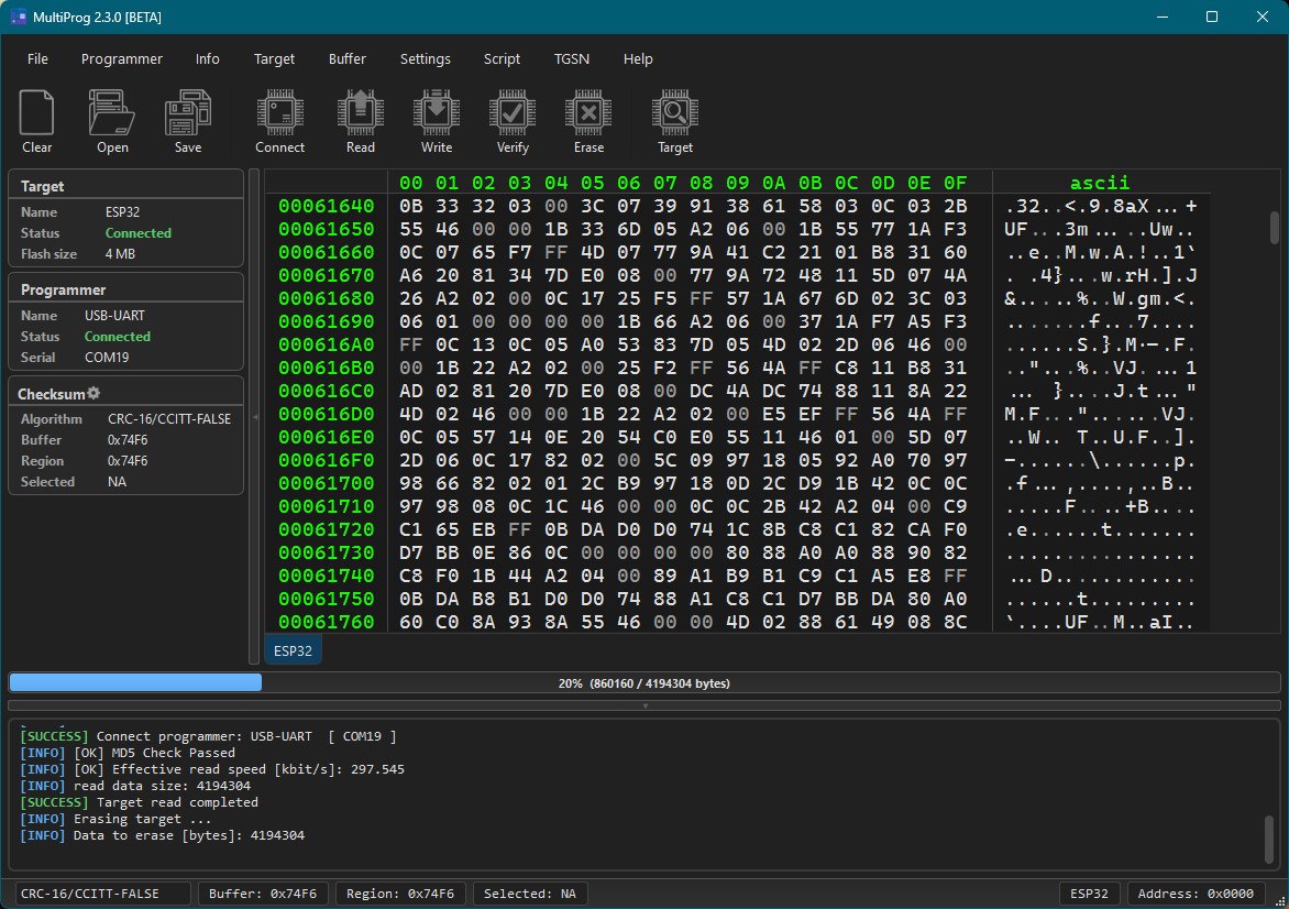
MultiProg Interface
Interface Elements
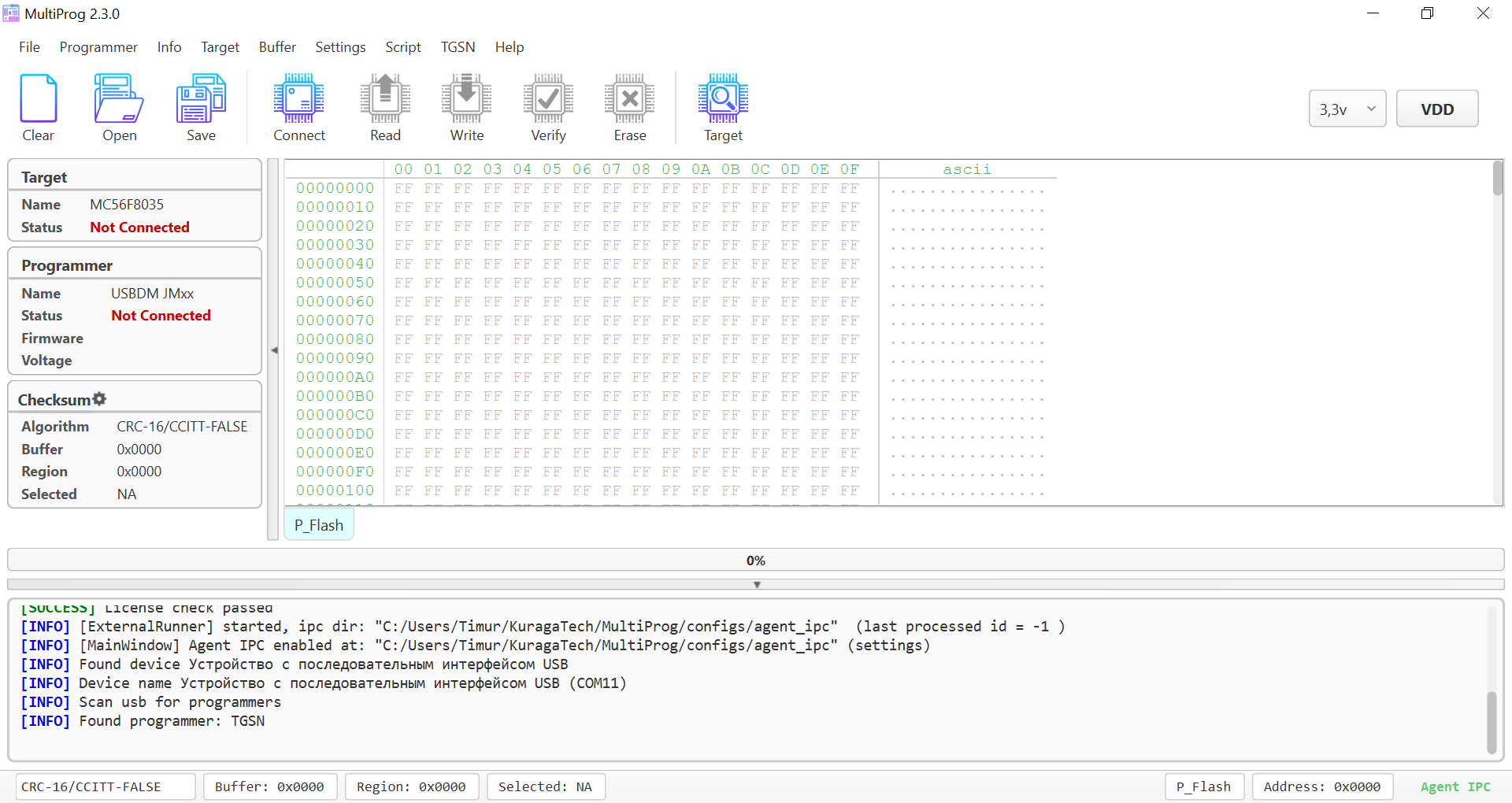
- menu – the main menu of the program.
- actions toolbar – the most commonly used actions, duplicating the menu.
- additional actions – actions applicable to a specific programmer or controller. These change depending on the selected controller/programmer.
- programmer & target info – a brief summary of the connected programmer and controller.
- hex buffer – visualization of all memory segments of the controller in the form of a hex buffer.
- log – logging window.
- memory/address bar – shows the name of the selected memory segment in the hex buffer and the highlighted address.
Basic Programming Actions
connect– establishing a connection with the programmer and the controller.read– reading each memory segment according to the memory map, saving to the dump buffer of each segment.write– writing each memory segment from the buffer without prior mass erasure.verify– comparing each memory segment for correspondence with the contents of the buffer.erase– mass erasure of each segment from memory if no other erasure mechanism is provided by the controller manufacturer.
Hotkeys
| Shortcut | Action |
|---|---|
Ctrl+T | Target search |
Ctrl+H | Recently selected targets (history) |
Ctrl+U | Favorites |
Ctrl+I | Open Connection image |
Ctrl+M | HEX buffer compare mode |
Ctrl+F | Context-aware search — log if log is focused, hex buffer otherwise |
Ctrl+G | Go To address in hex buffer |
Ctrl+B | Select Range in hex buffer |
Ctrl+0 | VGBN — Select Zero Block (handy for RL78 / NEC swap-zero workflows) |
Ctrl+L | Open Script Console |
Quick Start
The usual order of actions:
-
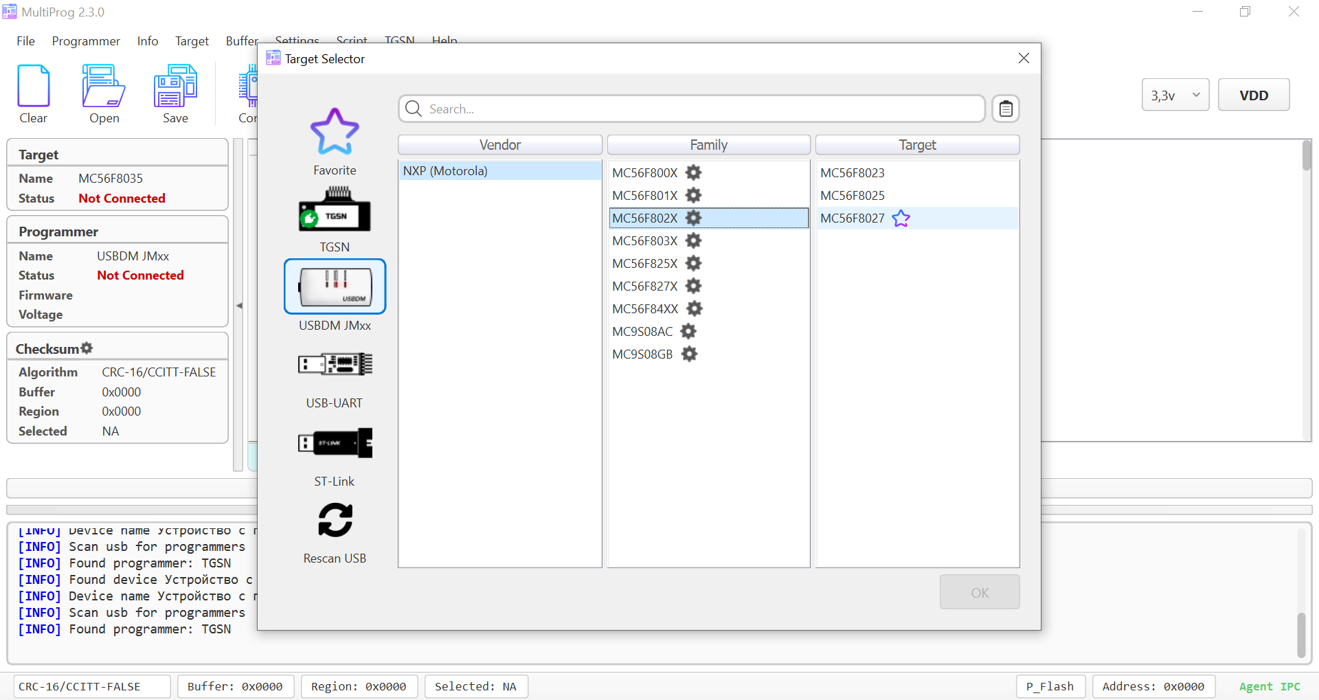
Open Target in the menu or in the actions toolbar.
-
Select the programmer and controller, then click OK.
-
Make sure you have read the setup guide for the programmer. For example, see the USBDM guide.
-
Check in the menu Info->Connection Image; there might be a connection diagram for your controller.
-
Connect the programmer to the controller and click Connect.
-
After a successful (SUCCESS) connection, all actions (Read, Write, Erase, Verify) will become active.
-
Congratulations, you’re all set! 🚀
Hex Buffer and Memory/Address Bar
The hex buffer is a mirrored representation of the controller's memory within the program.
In the hex buffer, there can be one or more tabs with memory segments. Switching is done by clicking on the tab with the segment name.

Quick Navigation
By clicking on the address field, you can quickly jump to a specified offset.
Copying a Line in Hex/Text
By right-clicking, you can specify the copy format.
Determining Segment and Address via Memory/Address Bar
 Why does the address always show 0x00 for cell 0x00-0x01 in this video?
This controller (mc56f) has 2 bytes per memory cell.
Why does the address always show 0x00 for cell 0x00-0x01 in this video?
This controller (mc56f) has 2 bytes per memory cell.
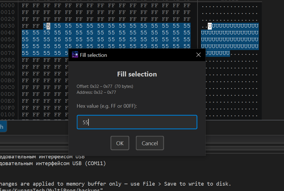
Editing the buffer (Edit / Fill)
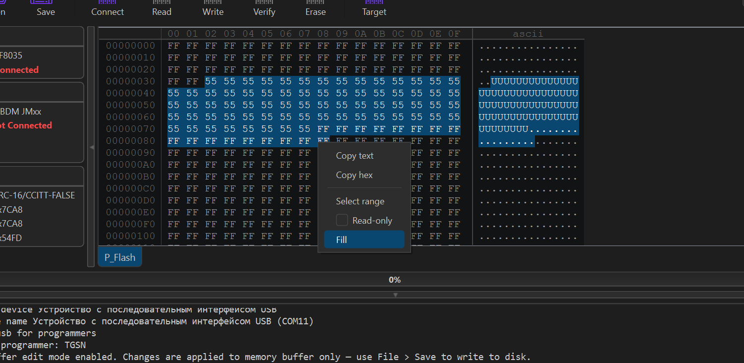
Right-click in the hex buffer to open the Edit / Fill context menu:
- Undo / Redo — full history of buffer edits, also available from the edit menu.
- Fill — fill a range with a constant byte or pattern; the dialog validates hex on the fly and shows the active address.
- Changed bytes are highlighted, so you can spot every edit before saving.
- When you enter edit mode the buffer is automatically backed up.
Select Range (Ctrl+B)
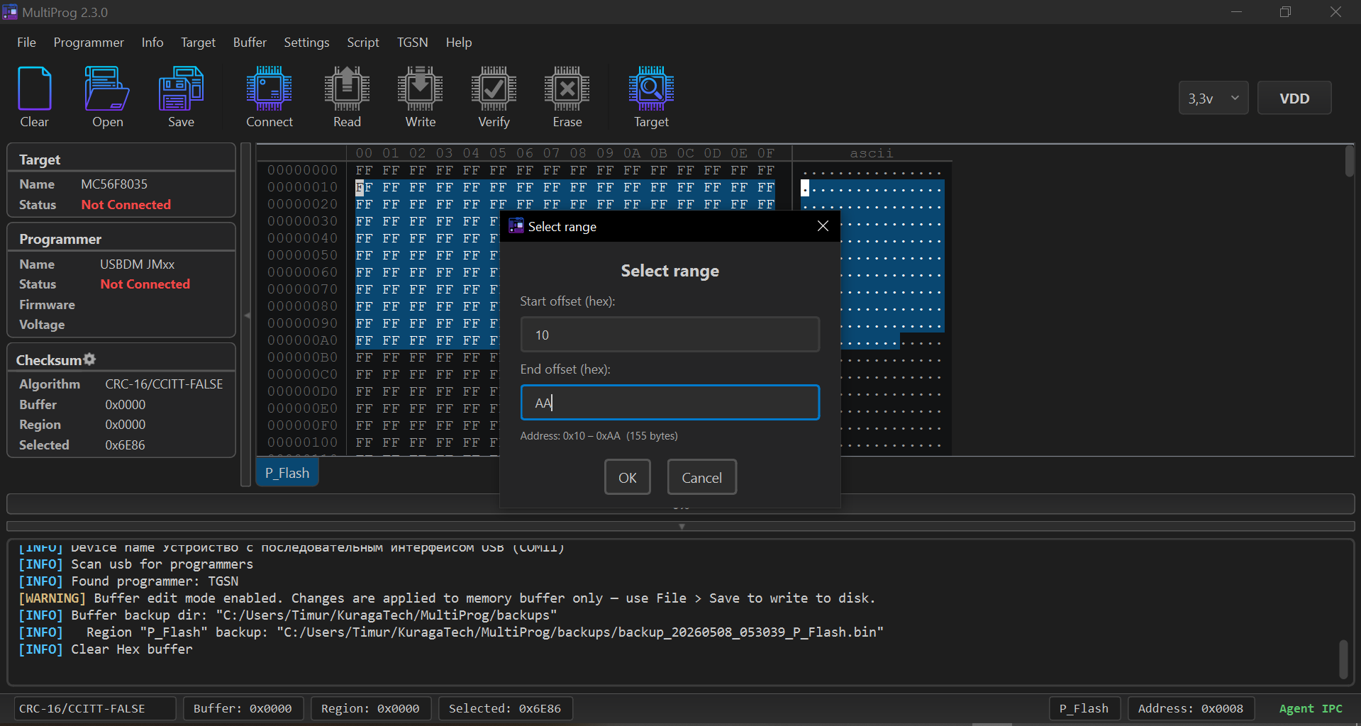
Open Select Range (Ctrl+B) to select a hex-buffer fragment
by offset (start address + length). Useful for partial saves and
checksum scopes.
HEX compare (Ctrl+M)
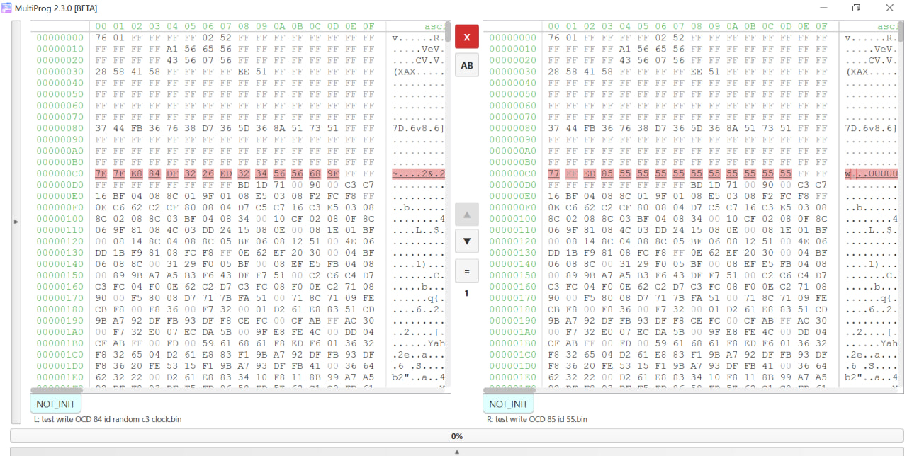
Opens a side-by-side HEX Compare dialog with two viewers, diff highlighting, synchronized scrolling, and forward/back navigation through the differences (cyclic, across tabs and regions). Sources: current buffer or any imported file (binary or S19). While Compare is open, the main buffer is locked for editing.
Working with Firmware Files
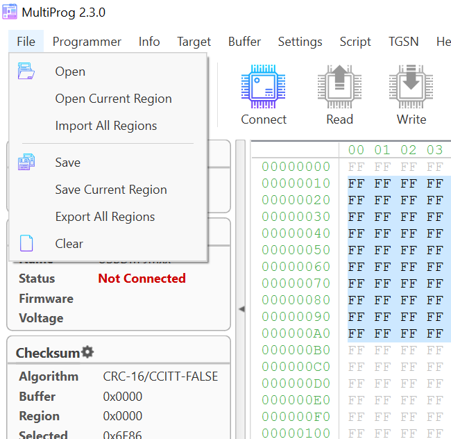
The File menu has 6 items (Open / Open Current Region / Import / Save / Save Current Region / Export).
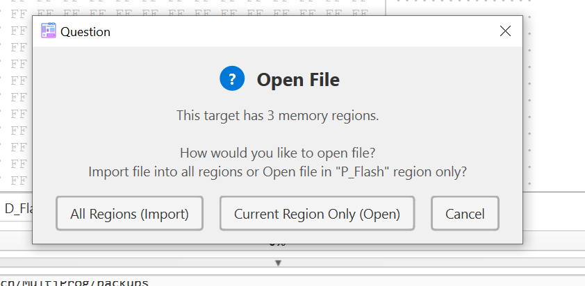
On a multi-region target you'll be prompted to import or load a single region.
The File menu has six entries:
- Open — smart open. On a single-region target it loads the file into that region directly. On a multi-region target it asks via a dialog: All Regions (Import) / Current Region Only (Open) / Cancel.
- Open Current Region — loads the firmware file into the currently active tab only (no dialog).
- Import All Regions — loads all regions from the selected file in one go.
- Save — smart save. Single-region: saves directly. Multi-region: asks All Regions (Export) / Current Region Only (Save) / Cancel.
- Save Current Region — saves only the currently active region (no dialog).
- Export All Regions — saves every region into one file.
The toolbar buttons Open and Save call the smart variants
(same as File > Open / File > Save).
Supported extensions: .hex, .s19, .s28, .s37, .srec, .mot,
.sx, .s2, .s3, .bin. The format is determined by the extension.
For a multi-region target, prefer Import / Export in S19 format
(aka .mot, .srec) — the addresses of every region are preserved
in a single file.
Difference Between Import/Export and Save/Options
Segments (regions) in this case refer to memory sections of the microcontroller (see memory map); not all controllers have multiple memory segments.
- Export in S19 format adds each segment in SREC format.
- Export in bin format, starting from 0x00 to the initial address of the first memory segment, fills the file with 0xFF. It then adds the first segment to the file, followed by adding 0xFF up to the start of the next segment, and continues this process until the entire buffer is loaded.
Therefore, Export in bin format is not recommended without necessity, as the firmware file may become very large.
- Import in s19 format parses the srec file, extracting and loading each segment into the buffer.
- Import in bin format calculates the initial offset based on the address of the first memory segment, extracts data from the file starting at (initial offset) and of size (segment size), and does this sequentially for each segment in the buffer.
- Save in bin format simply saves segments as they are, where zero offset = start of the segment. In s19, it uses addressing.
- Open in bin format loads the selected memory segment with a zero offset, i.e., as it is in the file. In s19, it uses addressing.
I saved the read USBDM firmware for DSC (MC56f) and it is larger than it should be
This controller (mc56f - DSC) has 2 bytes per memory cell. Therefore, if there are addresses 0x0-0x7FFF, the byte count is doubled.
Themes
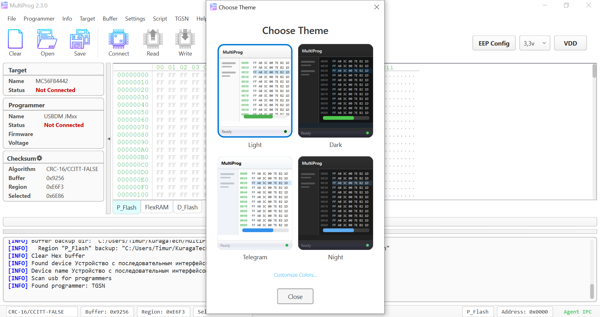
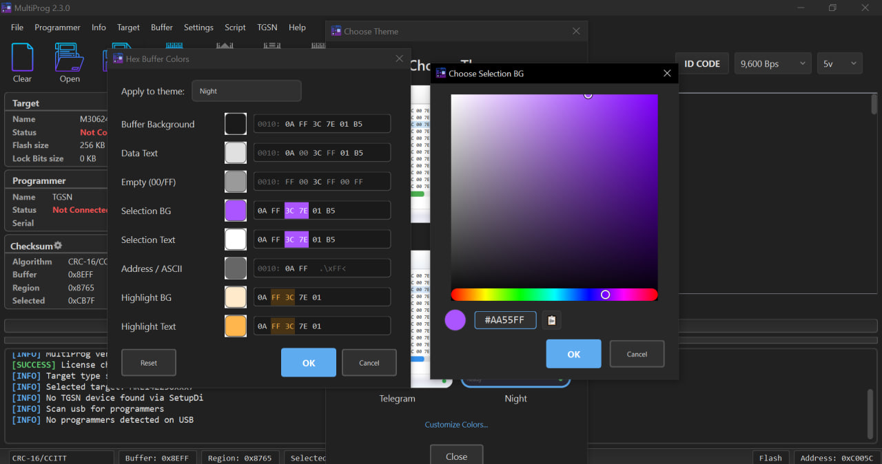
Four built-in themes are available — Light, Dark, Telegram,
Night — switched on the fly via Settings > Theme.
- User theme editor — tweak colors of the entire UI, save your own theme.
- Hex Buffer Colors editor — separate editor for hex-buffer colors (background, edited bytes, mismatch, selection) with mini-previews and live theme preview.
- The window title (DWM), icons, hex viewer, logger, dialogs, scrollbars, and tabs render correctly in every theme.
Checksum Settings
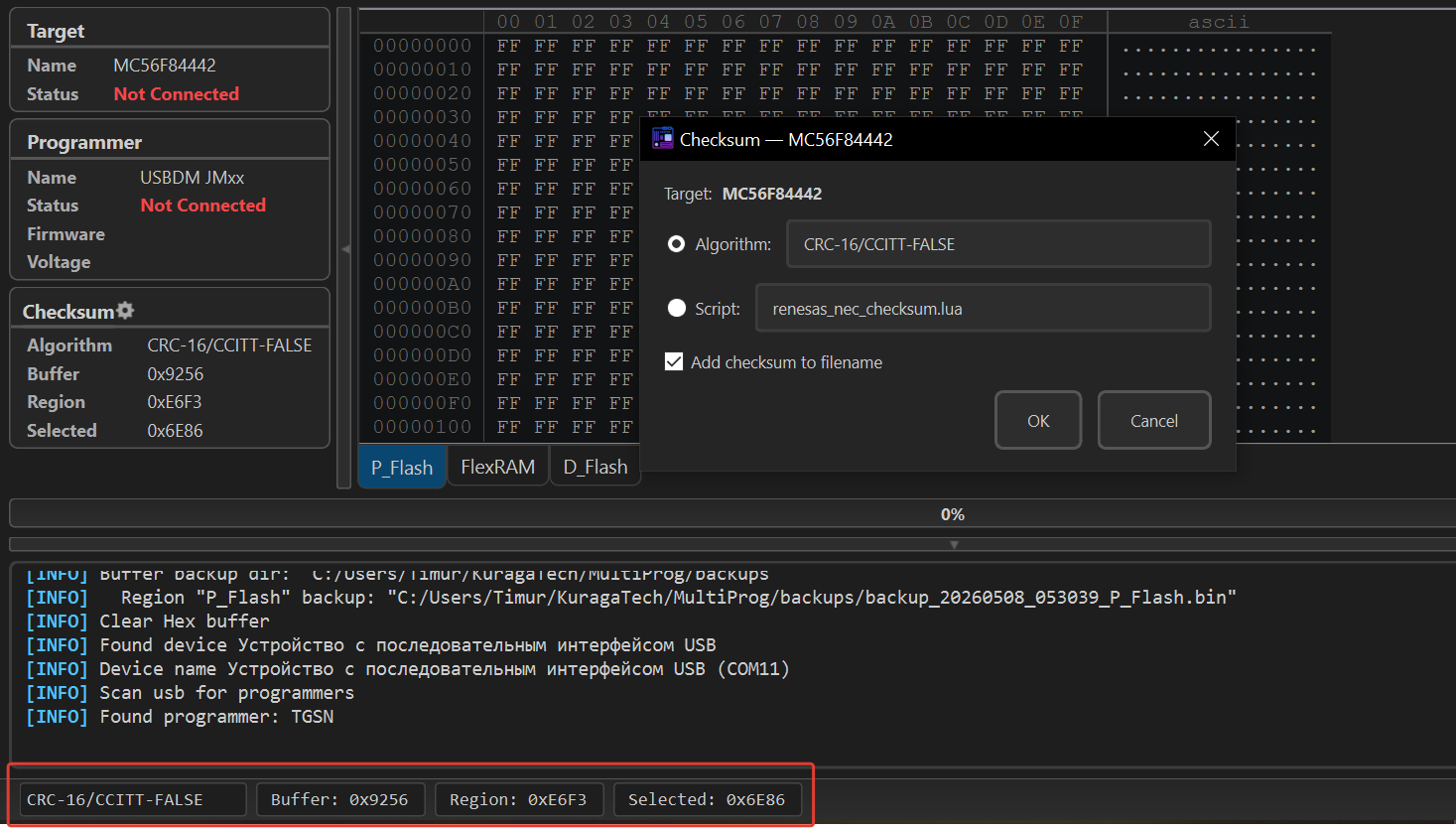
Settings > Checksum Settings opens the new profile-based checksum
dialog:
- Profiles: pick from a saved set of CRC algorithms or create your own.
- The full set of
crccalc.compresets — including 16 new algorithms added in 2.3.0;KERMITis renamed toCCITT. - Custom Lua-based calculators — see Lua scripts.
- The active checksum is shown in the Checksum info panel in the left sidebar (auto-resizing) and in the status bar.
Ctrl+0recomputes the RL78 / NEC checksum quickly.
Mismatch navigation
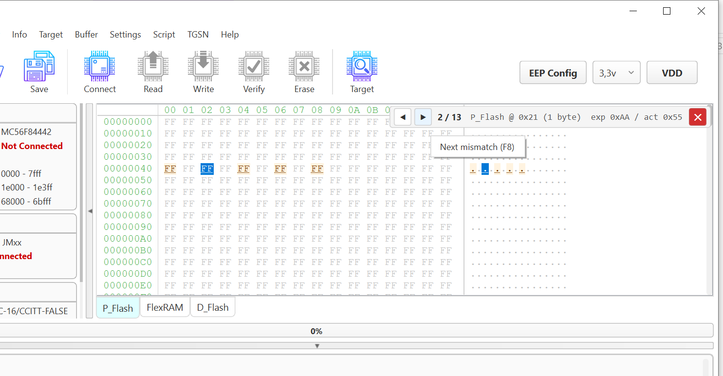
After a verify operation that finds differences, a Mismatch
navigation panel appears at the top of the hex view. It lets you
jump forward / back through the mismatches cyclically, across tabs
and regions. The panel is hidden automatically on buffer change,
write, erase, and edits.
Favorites and History
Ctrl+T— Target Search.Ctrl+H— History of recently selected targets.Ctrl+U— Favorites. Add any target to favorites with the gold star; the Notes column lets you add a free-form note next to each entry.- On load, stale entries (targets that no longer exist in the database) are cleaned up automatically.
Lua scripts
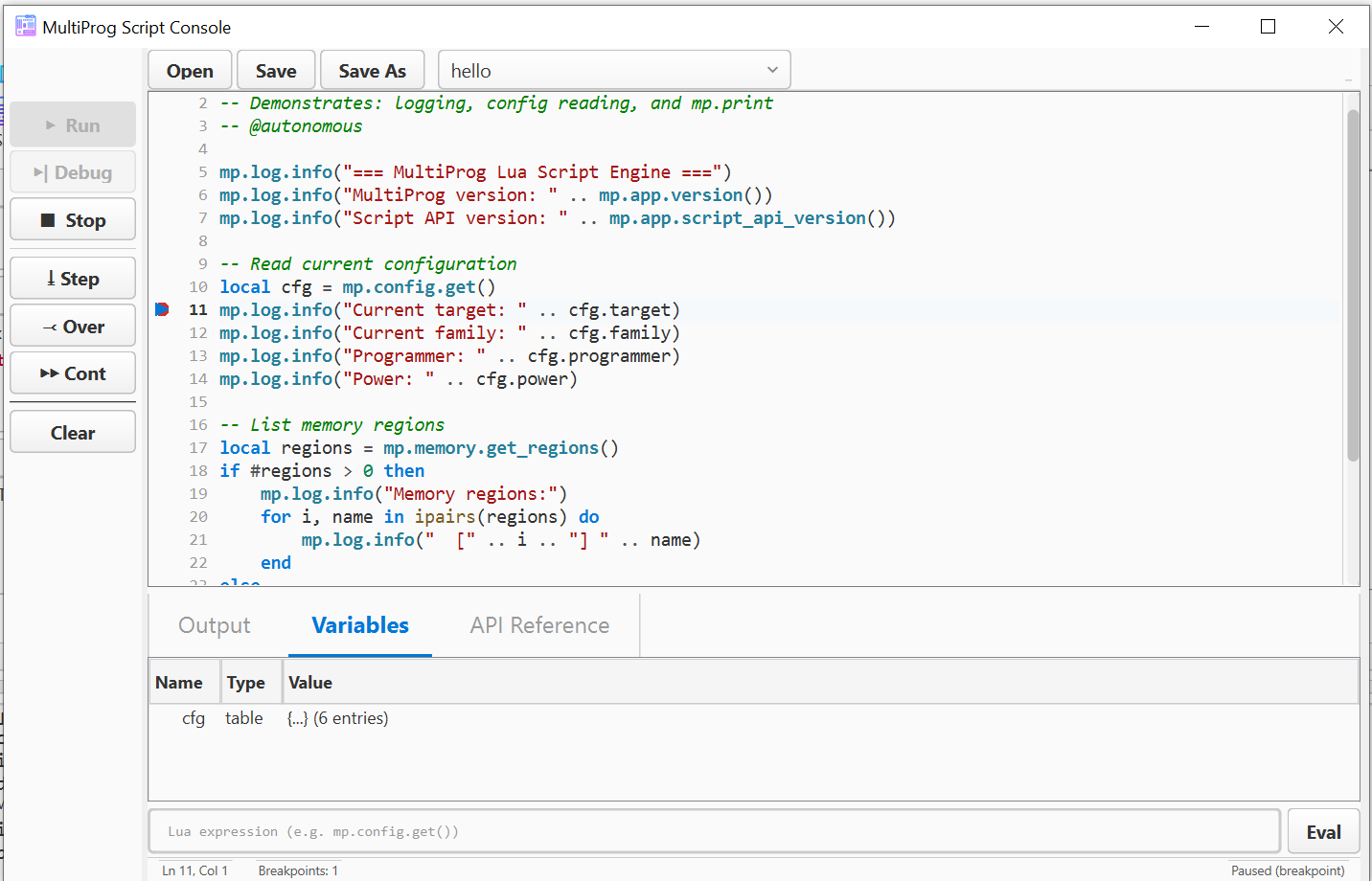
Starting from 2.3.0, MultiProg ships with a Lua scripting engine (Lua 5.5.1) and a Script Console.
- Script Console — separate window with code editor, syntax highlighting, autocomplete, debugger (breakpoints, step), and an interactive REPL.
- Full API — about 235 functions across 12 modules
(
mpcore,mp.backend,mp.config,mp.memory,mp.file,mp.checksum,mp.targets,mp.target_builder,mp.log,mp.ui,mp.utils,mp.app). - Custom checksum scripts — Lua scripts marked with the
-- @checksum-scriptheader act as user-defined checksum calculators with the result shown in the status bar. - Bundled examples —
scripts/examples/:batch_flash.lua,mass_production.lua,read_and_verify.lua,firmware_analysis.lua,hex_patch.lua,target_search.lua,create_target.lua,create_tgsn_target.lua,renesas_nec_checksum.lua,stm32_g0_g4_export_mot.lua,stm32f7_option_bytes_stvp_convert.lua, and more. - Watchdog — a hung script is auto-stopped after 10 minutes.
AI Agent IPC (preview)
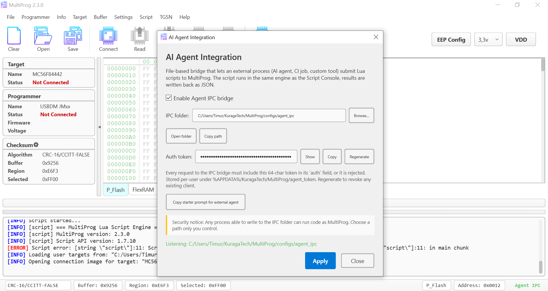
For full coverage — settings dialog, CLI flags, IPC folder layout, safety notes — see the dedicated AI Agent page.
Settings > AI Agent Integration enables an IPC bridge for driving
MultiProg from external AI agents (Claude, Cursor, etc.):
- Token authentication (
agent_tokenin%APPDATA%/KuragaTech/MultiProg/). --agent-modecommand-line flag — start with IPC enabled out of the box.- "Copy starter prompt for external agent" button — copies a ready prompt describing the API for paste into the agent.
Settings - Settings Menu
-
License — information about your license and activation.
-
Theme — switch between Light / Dark / Telegram / Night, edit user themes, edit Hex Buffer Colors.
-
Checksum Settings — checksum profiles, CRC algorithm selector (see Checksum Settings above).
-
AI Agent Integration — enable / disable the IPC bridge, view / regenerate the agent token.
-
Debug mode — runtime flag for extended operation logging (
[read-diag]/[trim-diag]markers in the log), no application restart required. -
Download log — saves the current session log to a specified path; it may come in handy.
-
Reset default config — removes settings and restores defaults.
-
Check updates — checks for and installs updates.
Info->Connection image
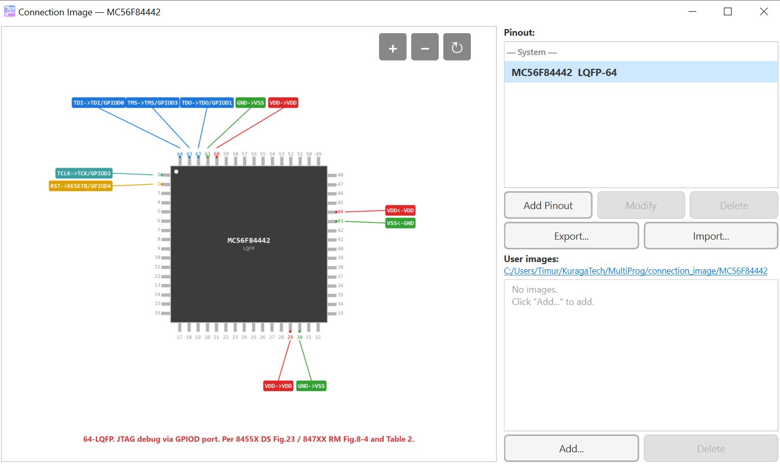
The Connection image (Ctrl+I or Info > Connection Image) shows
the wiring between the programmer and the target MCU.
In 2.3.0 this is auto-generated from the JSON pin description of the target device:
- Supported packages: 4-sided QFP / LQFP / TQFP / QFN / PQFP /
PLCC, 2-sided SOIC / SSOP / LSSOP / TSSOP / DIP, special
BGA / Connector1Row / Connector2Row / AbstractTable;
rectangular layouts (e.g. PQFP 14×20 mm for M16C). JSON aliases:
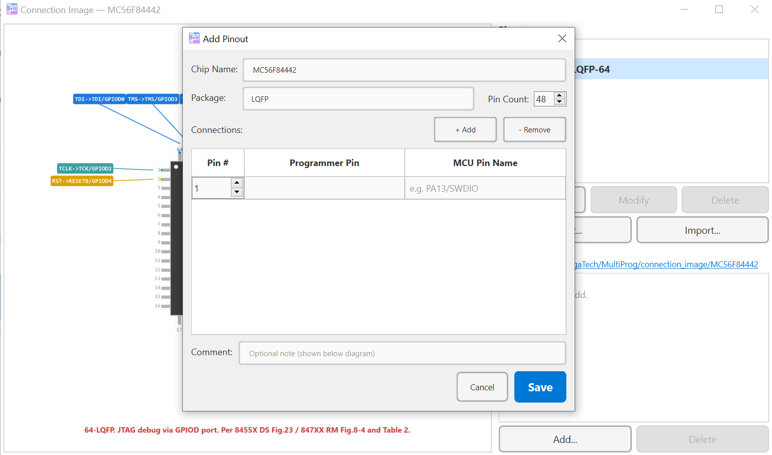
HWQFN/HVQFN→QFN,LFQFP→LQFP,PSDIP→DIP. - Visual pinout editor (
PinoutEditorDialog) with a live preview — edit pin assignments directly in the GUI. - Connection table programmer↔target (
AbstractTable) — alternative tabular view of the pin mapping. - Package rotation to align the diagram with the physical chip orientation on the board.
- NC pins — visual landmarks for non-programmable package pins (pin labelled on the package but not routed to the programmer).
- Pinout Export / Import through the configurator — share or back up your pinouts.
- User-built diagrams: you can add your own diagram for a new chip by editing the JSON pin description.
Built-in coverage in 2.3.0 includes M16C (35 targets / 68 diagrams), R8C (183 / 263), RL78 (139 devices across 8 families), NEC 78K0 / Kx1+, M32C / R32C, ESP, TMPM370 / TMPM470, HART, DSC, HCS08 / HCS12.
For step-by-step instructions on creating a custom Connection image
(JSON shape, NC pins, programmer pin names, Pinout Editor, Lua
mp.target_builder) see Custom Connection image.
Help-about (version)
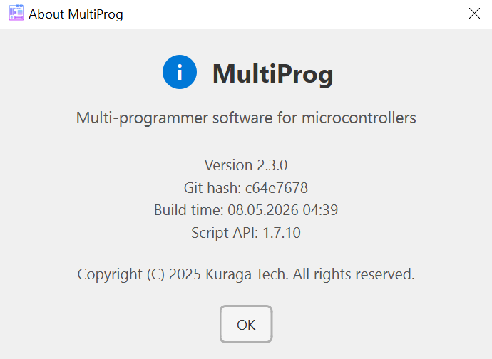 You can view the version, build time, and hash of the program in
menu->Help->About.
You can view the version, build time, and hash of the program in
menu->Help->About.
This may be useful when contacting support.